Recently I got into Ham Radio, and I made a 140mhz antenna for myself, and after SWR testing and tuning by W5AAF, it works very well. I was shocked, not having built an antenna before, and being very new to the amateur radio hobby.
My success stemmed from having a fairly straight forward set of construction plans, and a good Elmer, Al! I began with the plagiarized plans below, thanks WD4JR.
The plans shown below are modified to demonstrate this 223mhz antenna project.
First, the dimensions and lengths were needed. I built the first version from construction plans we found on the internet. Unfortunately, the SWR readings were too high after my brother tested the antenna with his Bird watt meter. Probably it was a result from using plans designed to utilize 300ohm ladder line, not 450ohm.
We scratched our heads a while, and eventually my brother found an online calculator which gave us the various measurements necessary for construction. Measurement Calculator
Good antenna article
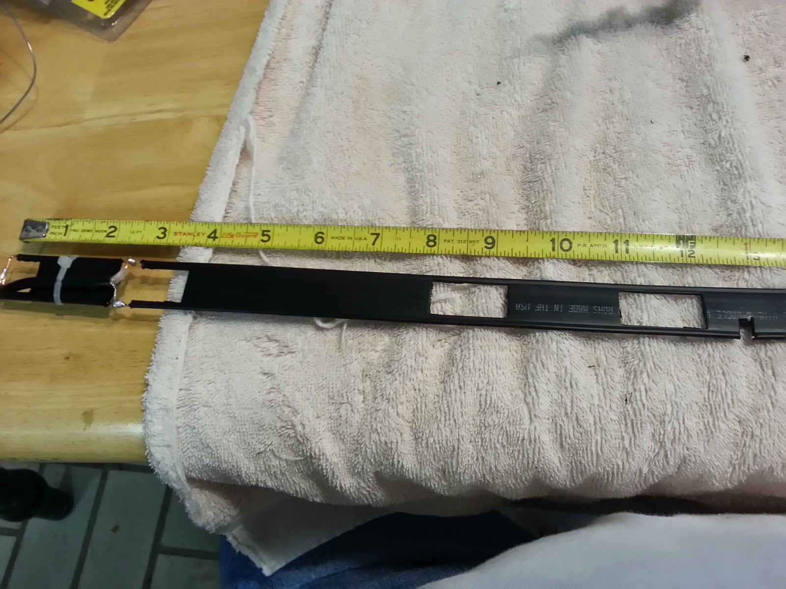
As you can see in the first photograph, a little too much cutting happened, as a result of the prior plans. Some lengthening was in order. Do not fear, as the 450 ohm ladder line is pretty robust.
My soldering is not pretty, but it gets the job done.
Remember to check continuity after soldering the coax! My brother tested his antenna and the SWR readings are extremely good, needing very little tuning. Al's antenna's SWR readings were perfect, and needed no trimming or adjustments at all.
Robert's antenna is in service and he gets excellent signal reports.
Before final assembly, be sure to have the SWR's checked with a good meter to tune the antenna.
Materials list:
450 ohm ladder line
a short length of 50 ohm RG58A/U coax and connector
wire ties
Five feet of 1" PVC pipe, thick wall preferred
caps for PVC pipe
caulk
 |
| Detailed construction plans |
 |
| Solder is ugly, but she works well |
 |
| Antenna innards |
 |
| Use gravity to help slide the antenna into the PVC pipe |
 | |
| Top PVC Cap with holes drilled for wire ties. Caulk keeps the weather out. You might want a weep hole in the bottom cap to allow for condensation drainage. Multiple wire ties are used to allow the antenna innards to hang from the top cap |
 |
| Finished Antenna for KF5ZMC |
 |
| Al's antenna: First Step is to solder the end |
 |
| Al's antenna: bottom portion |
 |
| Al's antenna: measurement is kinda close |
 |
| Al's antenna: Notched one lead |
 |
| Al's antenna: Wire ties are used to hang the antenna inside the PVC pipe |
 |
| Al's antenna: Bottom cap has two holes, one for coax, one for draining any condensation. |
No comments:
Post a Comment